Introduction
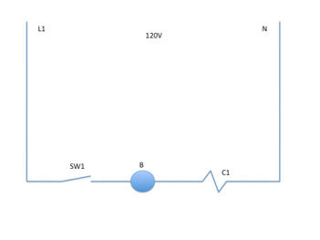
In earlier sections of this manual we spoke about what the requirements of a complete circuit are. You should remember that these as a source, a switch, a path and a load. An example of the source could be you wall outlet with 120V power. An example of the switch would be the light switch on the wall and an example of the load would be the light on the ceiling. The path would be the copper wire that connects everything together.
Now we must take the circuit layout a step further. What happens if you need to have more than one switch, for example a safety switch on a furnace or safety switches on a boiler? The safety switch is not the primary switch, but it also has to prevent electricity from reaching the load. This is an example of a series circuit.
Another scenario we must look at is if there are two loads that we want to provide power with off of one switch. A common household example of this would be having two outside lights, one on each corner of your house on one switch inside. You turn the switch on and the circuit gets power to both bulbs. Both bulbs must burn at the same brightness and power. If one bulb goes out the other one must remain burning. This is an example of a parallel circuit.
Now we are going to look at both series and parallel circuits a bit further and then do two shop projects that will demonstrate the differences.
Series Circuits
A series circuit exists when:
– The flow of electrons (electricity) must pass through a series of components.
- Switches that control loads are wired in series with these loads.
Loads in series
Loads in series (as shown in figure 11 and figure 13) are not common. However you must understand how they work for proper troubleshooting.
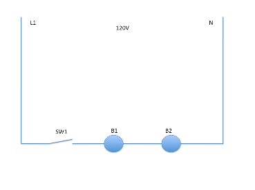
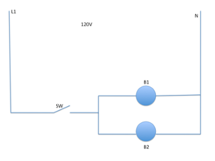
1. When 2 or more loads are wired in series the voltage applied to each load will split. In other words, as the example shown in diagram figure 13 shows there are two light bulbs wired in series. Even though they are 120 Volt light bulbs neither one will get the full 120 volts. They will split it.
2. The voltage drop, or the voltage of the entire circuit, will add up to source. In figure 13 if you take a voltage reading across bulb 1, and a voltage reading across bulb 2 they will add up to source, which in this case is 120 volts.
3. The amperage in all series circuits is the same at any place throughout the whole circuit. Amperage flows through all of the loads equally. You will get to try this later in the shop project.
The important point you must remember about series circuits is that the voltage changes but it adds up to source and the amperage remains constant. Because the voltage changes series circuits are not used in the HVAC industry that often for loads. You will however see series circuits as control circuits.
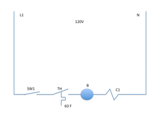
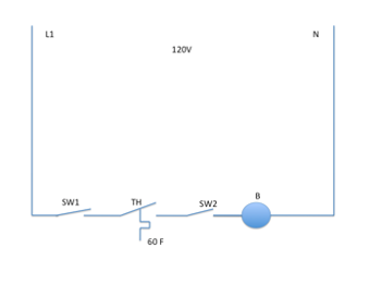
Control circuits are circuits that provide control to a single load. Figure 14 shows a series circuit, which has three switching devices and powers one load, which in this case is a relay coil.
When you have a series circuit with two loads (in our example light bulbs) and one of the loads burns out the other one will not get any power because the burnt out bulb will act as a switch that is open, preventing the flow of electricity from one bulb to the next or back to neutral.
Parallel Circuits
Our next example was one of a single switch that controlled more than one load. This is an example of a parallel circuit. Figure 15 shows a basic parallel circuit where one switch controls two light bulbs supplying each with the same amount of voltage. If one of these bulbs burns out the other one will still remain powered. This is because there is a separate path (or wire) to each bulb.
Parallel circuits are the most common circuit in the HVAC/R industry. An example of the use would be the compressor and the outside fan on an Air Conditioning Condensing unit. You want them to both come on at the same time but you do not want them to split voltage.
Looking at figure 15 you will notice that each branch only contains one load. Each branch could have a separate switch of controlling device in series with it. This is shown in figure 16.
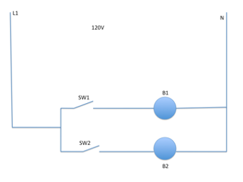
The voltage to each load is the same as the source voltage and it is equal to each load. In figure 16, light bulb 1 will have the same voltage as light bulb 2. If you open the switch to light bulb 2 the voltage across light bulb 1 will not increase or decrease, it remains the same.
The amperage adds up across the whole circuit but is stable in each branch. The amperage (or current flow) is based upon the resistance of each load.
Glossary of Key Terms
Series Circuits: Where components (loads and switches) all share a single path for current flow. Voltage is shared across each load and each load gets less than the full source voltage. Most often used in the HVAC industry for control circuits.
Parallel Circuits: Where components (loads and switches) have different paths for current flow. Voltage is source voltage across each load and each load gets the full source voltage. This is the most frequently used non-control circuit in the HVAC industry.
Control Circuit: A Circuit that contains switching devices that leads to a single load. Control circuits are most often series circuits and most often low voltage.