Introduction
Electricity is defined in Webster’s Dictionary as a fundamental element of nature consisting of negative and positive kinds of neutrons and electrons (Webster 362). You as the heating and air conditioning professional do not need to know this. However you do need to understand and know how electricity works. For the remainder of your career you will need to know that electricity is a positive and negative charge that is created by an electro-magnetic force.
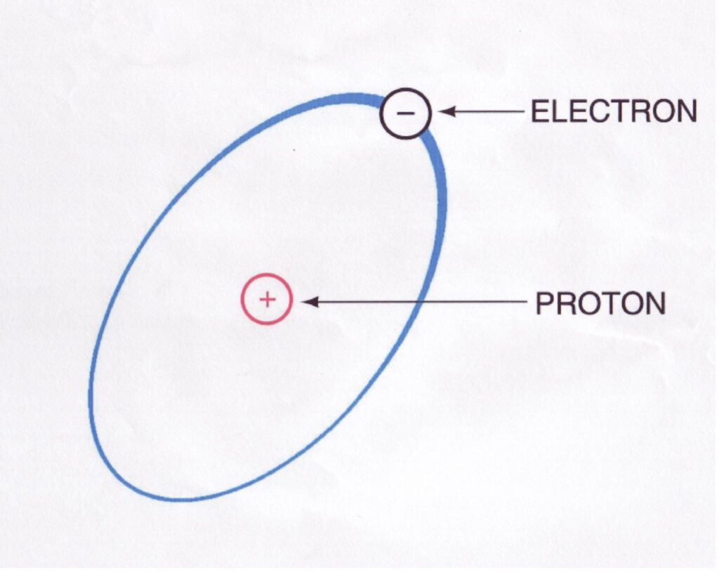
Figure 1 – Atomic Structure of an Atom (Porter and Chester Institute)
Electricity and electrical principles are one of the most important things to master as an HVAC technician. You can master the mechanical, the hands on installation and trouble shooting skills, but without a clear understanding of electrical properties, circuits, and meter use you will not be able to diagnose close to 75 to 95 percent of the problems you come across.
Electricity starts with the most basic form of matter in the universe, the atom. We are not going to talk much about atomic theory but you need to know that atoms are formed of protons, electrons and neutrons. The protons have a positive charge and the electrons have a negative charge. These charges combined with a proper conductor are how electric current is generated.
The law of charges state that like charges (poles) repel each other. So negative repels negative and positive repels positive. Opposite charges attract. Positive attracts negative and negative attracts negative.
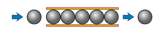
Different materials have a different strength of attraction, or saying it differently a different force required to move the electrons from atom to atom. A conductor uses substances that have easy to move electrons; this is molecules such as gold, copper and silver.
A conductor is a substance like wire, metal, earth, and water where the electrical current can pass easily. The human body is a good conductor that is something you must remember as you work with anything electrical. This movement of the electrons from atom to atom along a conductor is what allows electrical energy to do work.
An insulator is a substance like rubber, cloth, and glass that resists the flow of electricity. Insulators are found on the tops of power line poles and around wires.
An electro-magnetic force is one that is created by a magnet spinning inside a spool of wires. The current that is generated by the spinning magnet is sent out over the wires to do work. This is power, voltage, and amperage.
Electricity is produced by one of four methods. The first is by friction. This creates Static Electricity. The second is chemically; this is how it is created in your car battery. The third is using magnetism; this is how the power companies using generators create it. The fourth is by a thermocouple that we will discuss more in the gas heating section.
Voltage is the potential to do the work and it is measured in Volts. Current is the movement of this voltage it is measured in Amperage. There are two types of current that we will use in the HVAC industry. These are Alternating Current (AC) or Direct Current (DC).
A circuit is a path for electricity to follow. Every circuit has a source, which is where the power comes in. Every circuit has a path that is wire for the electricity to travel, every circuit has a switch to turn it on or off, and every circuit has a load which uses energy to do something. A household lamp is a circuit. It has a source (the plug), it has a switch (a switch), it has a path (the wire from the plug to the switch to the bulb and back to the plug), and it has a load (the light bulb) that creates heat and gives off light.
Alternating current
Alternating Current is what you have in your home or business. It uses a constantly changing polarity. Polarity is the Positive and Negative sides of the magnet or circuit. Frequency is the number of times per second that the polarity changes. The standard in the United States is a frequency of 60 Hertz. In Europe and other continents the standard is different with most of these other areas using 50 Hertz.
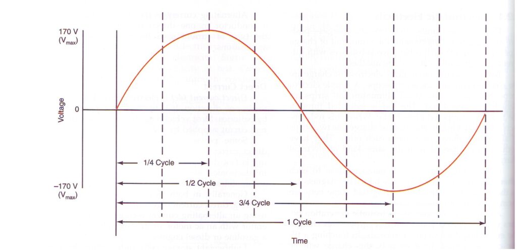
The peaks on each side of the alternating current (the positive and negative points) are considered the voltage. In most homes the electrical outlets are 120 Volts. This means that there is a peak of 120 volts to the positive and 120 volts to the negative. The middle position is called Neutral.
The diagram below is a snapshot of 120 Volt Alternating Current.
Direct current
While alternating current is a wave pattern, direct current is a straight line. Direct current is most often used in car batteries and automotive uses. Direct current is also used in computers and smaller electronics. If it is small, runs on batteries, and directly attaches to a computer it is most likely direct current. In direct current power travels one direction, from a positive to a negative.
Line voltage
One of the concepts you will need to understand is the difference between line voltage and control voltage. The voltage that comes in off the power line is line voltage. For example you plug a light into the wall at your house this light uses line voltage. If you have a clothes drier at home this also uses line voltage. Line voltage is usually over 100 Volts and is directly connected to the power company through a circuit breaker or fuse.
Control Voltage
Control voltage is much lower than line voltage. In most HVAC applications control voltage is 24 Volts AC, or 24 VAC. The line voltage is taken and reduced by the use of a transformer and lowered to 24 volts. This is done most often for safety. In most states it is not required to have an electrician wire control voltage but make sure you check with your local building code for details.
Resistance
Resistance is the final measurement that you will use. Resistance is the force that opposes electrical flow. Resistance of a wire is extremely low and thus electrons can move very fast along that wire. Resistance is measured in Ohms.
Introduce first 5 symbols
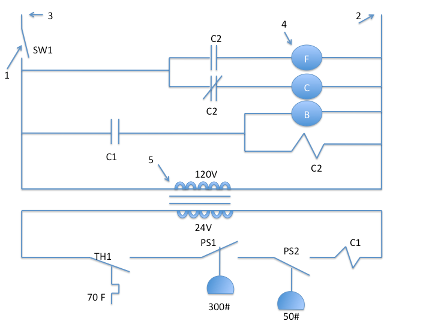
When you see a circuit drawn on paper it is drawn using symbols and lines. This type of drawing is called a schematic circuit. A sample of one of these circuits is figure 3. Now, let’s take a look at the most basic of the symbols you will need to know. There are many more symbols you will need to know and a full symbol sheet is in the back of this manual. If you are taking this class as a part of a school program you are required to memorize all of those symbols. If you are doing this on your own you should memorize these as fast as you can because it will make your life easier.
Switch
The switch is a basic component of all circuits and all circuits are required to have one. It either stops the flow of electrons or lets them pass. It is the equivalent of a valve on a sink. The valve is open the water flow and when the valve is closed the water stops. However when you are talking about a switch you must remember one major difference. When the switch is open there is no flow of electrons. When the switch is closed the electrons flow. Figure 3 point 1 is a single pole, single throw switch. It is either on or off (open or closed).
Source
The source of a circuit is where the power or current comes in. Normally this is a plug, but it may be a fuse box or breaker. The source is shown at the top of the schematic diagram with labels on the lines starting the diagram. Figure 3 points 2 and 3 show the source.
Light Bulb
Every circuit must do something. The something is called a load. In figure 3 the load is a light bulb. Loads can be motors or heaters or compressors, but they all do something and all use power. The symbol of a light bulb, a very simple load is found in figure 3 point 4.
Transformer
A transformer takes and converts the voltage from line voltage to control voltage. A transformer is shown in figure 3 at point 5. You will notice that the transformer acts as the source for the second circuit on the lower side of the diagram. So a transformer is both a source and a load. On the line voltage side the transformer is a source. On the control voltage side the transformer is a load.
Fuse
A fuse protects the circuit from using too many amps. The lower the resistance the more amps it uses. The higher the amperage the faster the current moves. The faster the current moves the more heat is generated in wires. So, to protect against over heating and fire most circuits have a fuse. A fuse is a basic protection against a short circuit or a circuit without a load.
Safety
In any introduction to electronics it is important to talk about safety. Electrical current can kill you. If it doesn’t kill you it can harm you severely. It can also harm your co-workers, burn the house down, or cause parts of a system you are working on to go up in smoke.
Electricity will always look for a path to ground. The path can be a screw driver not properly grounded or it can be a piece of sheet metal in contact with a bad heater element. Make sure you always know if power is turned on or turned off.
For these reasons we insist you follow these procedures in shop exercises:
- Make sure everything you are working on is unplugged and turned off when you begin an assignment.
- Remove all jewelry (rings and watches)
- Watch yourself and those around you. It is easy to be pushed into a live circuit.
- Do not work on live circuits unless absolutely necessary.
- Stand on dry non-conductive surfaces when working on live circuits and using electric tools.
- Check all circuits for voltage (power) before doing service work.
- Tag and lock all electrical disconnects when doing service work (lock out / tag out).
- Never bypass electrical protective devices (safeties, fuses, etc).
- Don’t under estimate the danger of electricity.
- Do not use tools with frayed or damaged cords.
- Wear eye protection.
- When adjusting power tools unplug them.
- Do not overload electrical circuits.
- Use black wire for line voltage source.
- Use white wire for line voltage neutral.
- Use red wire for control voltage source.
- Use orange wire for control voltage common (or neutral).
- Your instructor MUST check all circuits before you power it up. That means before you plug it in and turn it on the instructor must check it. Make sure the instructor initials your lab sheet.
Remember, electricity is dangerous because it is INVISIBLE!
Glossary of Terms
Voltage: The measure of potential energy. Voltage is the force that pushes electrons through an electrical circuit. Voltage is a potential difference from one point to another. Remember, the voltage across an open switch is source voltage. The voltage across a closed switch is 0. No potential difference exists.
Protons: The positive charge found in the atom.
Neutrons: The negative charge found in the atom.
Current: The measure of the rate of flow of an electrical charge through the circuit. It is measured in AMPS and sometimes described by the letter E.
Watts: The measurement of power. This is equal to one amp flowing with a pressure of one volt.
Resistance: Resistance is measured in Ohms. This is the measure of resistance to the flow of electricity. All electrical loads such as light bulbs, heat strips, motors and transformers have resistance.
Amperage: See Current.
Electricity: Energy that is capable of producing an electron flow. Electricity is energy. Electricity is capable of doing work.
Source: Where the voltage comes from. This is the starting point of the circuit.
Load: The power/work producing part of the circuit. The load could be the light bulb, the motor, the transformer.
Path: The wire or circuit board itself that connects the source to the load with a few switches or safety devices in the middle.
Switch: The gate or valve for the flow of electrons. An open switch does not allow electrons to pass. A closed switch allows electrons to pass.
Meter: A tool to measure amperage, voltage and resistance.
Transformer: A load and a source. The transformer changes the voltage and current from one level to another. In most HVAC circuits a 120V or 240V transformer steps voltage down to 24V (volts).
Schematic Circuit: A map or a drawing of an electrical circuit.
Insulator: A substance that resists the flow of electrical current.
Conductor: A substance that freely allows the flow of electrical current.