Introduction to meters
The meter will be your most often used tool as a Heating and Air Conditioning Technician. It is critical that you fully understand how it works and how to use it. The meter should be the first tool out of your tool bag and the last to go away. The meter is also the one tool you have that can save your life. You never touch any electrical components without first using your meter.
It is important that you read the manual that came with your meter. Specifically so you understand what your meter can do. Make sure you know how to adjust it to Ohms, A/C Voltage, D/C Voltage, Amps, and Temperature. These are the primary scales you will be using.
Types of meters
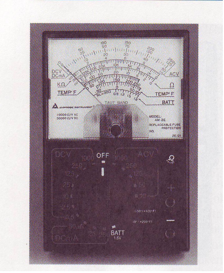
There are several brands of meters on the market, but they all combine into two distinct types. There are the analog meters like the one shown in figure 5 and there are the digital meters like the one shown in figure 6.
Analog meters have been the workhorses for many years. The analog meters where the first meters on the market, and they are still used in scientific fields today. They are extremely sensitive instruments and need to be calibrated frequently. While they do not stand up to the jarring of trucks and tool bags many of the better technicians still use them today when looking for exact equipment measurements.
Digital meters have almost completely replaced analog ones for the majority of the service technicians. Digital meters have multiple scales and most are auto-ranging. This means that you have the meter will adjust itself to the voltage and amperage scales it needs to display your readings. Make sure you are able to identify the scales that your meter reads.
Open Circuits
An open circuit describes a circuit that does not have a path for electricity to flow from one side to the other. The easiest way to describe the open circuit is the circuit you built in lab 2.1 with the switch open.
There is a potential that exists. There is 120V on one side of the switch and Neutral on the other. There is no way for that 120V to get to the Neutral until you close the switch. When you put the meter into Volts mode and put one lead on each side of the switch you should read 120V. The current will always flow through the meter rather than across an open circuit.
First rule of electrical diagnosis is “Voltage across an open circuit is always equal to the source voltage”. Engrain this concept into your mind and we can move on from there.
Complete Circuits
A complete circuit always includes a source, a path, a switch, a load, and a return to source. In the lab you built the source is one side of the 120V plug labeled L1. The switch is your light switch. The load is the light bulb (this could be a motor, a coil, or anything else that requires power and does work). The return to source is the N which is neutral.
The complete circuit will always have a complete path from Source to Neutral (or 2nd Source) with all switches and control devices closed.
On a complete circuit (using the circuit you built in 2.1 as an example) when you put a meter across L1 and N you will always get source voltage. Now, before you say this sounds the same as an open circuit let me explain why it is not.
On a complete circuit you have a load doing work. This load is consuming the source voltage that is available. So, the second rule of electrical diagnosis is “Voltage across a complete circuit is always equal to source voltage”. You can narrow this down even further to say “Voltage across a load or a series of loads will always be source”.
Now, taking this process a step further, a light bulb has a filament in it. This is what heats up when the current flows through it and this is what produces the light. If the light bulb burns out the filament opens and the current can no longer flow and heat it up. In this case the circuit becomes an open circuit, not because of a switch opening, but because of an “open” in the load. So, add to your electrical rules the concept that “Voltage across a non-working load is always equal to source voltage”.
Measuring Voltage
To measure voltage with your meter:
1. First turn your meter on and set it to Volts or V depending on your meters dial.
2. Make sure your leads are plugged into the correct plugs on the front of your meter.
3. Put the leads in parallel with (next to) the point in the circuit you are trying to measure. There is a diagram of this in figure 7.
4. Hold the leads steady without touching any of the metal to your fingers or each other.
5. Watch until the meter stabilizes on a number and that is your reading.
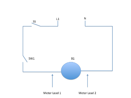
Remembering back to the point in the section above, if your meter reads 120V when you are reading across the switch 1 in your circuit that you built in 2.1 this means the switch is open. If your meter reads 0V when you are reading across the switch 1 in your circuit that means the switch is closed. If you read 120V across the light bulb and the bulb is on this means that the bulb is good. If you read 120V across the light bulb and the bulb is not on, this means that you have a burnt out bulb.
Measuring Current
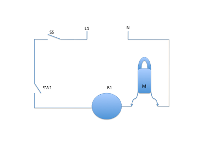
To read current or the amperage of a circuit first decide if you are going to put the meter in series with the circuit (actually put it into the circuit) or if you are going to use the clamps and measure it using the magnetic field around the wire that is generated by the electricity. See figure 8 and figure 9 for the difference between both methods.
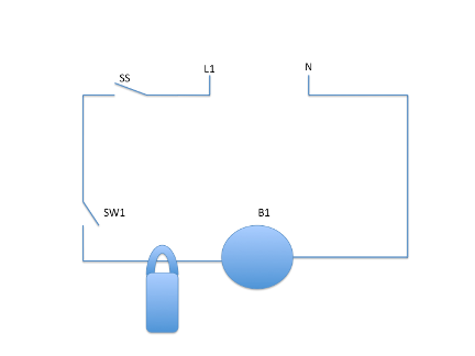
For most line voltage circuits in the HVAC industry you will use the clamps. For most control voltage circuits that you may need to troubleshoot you will put the meter into series with the circuit.
To measure current with the clamp on method:
1. Make sure the system is running.
2. Clamp the meter around a single wire and wait until the numbers stabilize.
3. This is your reading.
To measure current with the in-line method:
- First turn off the circuit at the source. This could be a service switch or a circuit breaker.
- Make sure your meter has the capacity to measure amperage in series for the voltage you plan on measuring.
- Check with the voltmeter as in the section above and make sure you do not have any voltage across the source.
- Decide where you want to check for amperage in the circuit.
- Disconnect one wire for the circuit and connect your meter in series with that wire.
- Connect one side of the meter from where the wire used to be connected and connect the other side of the meter to the wire.
- Turn your meter on and make sure it is set to Amperage.
- Next, turn on the power to the circuit and wait for the numbers to stabilize.
- This is your amperage.
There are two basic rules to remember for amperage in a circuit. First “the amperage across an open circuit will always be 0”. When there is no patch for electricity to flow from one side of the circuit to another there is no current or amperage. The second rule is “the amperage of a complete circuit will be as great as the path or wire supplying it can handle”. That means the larger the wire the more amperage it can support before it melts. Of course this is limited by the circuit breaker that is on the circuit.
Measuring Resistance
In section 2 where we spoke about resistance, resistance is the force opposing electrical flow. Every circuit must have a source, a switch, a path and a load. By design in most circuits the resistance is found in the load. This prevents wasting energy in parts of the circuit not doing any work?
To measure the resistance of a circuit:
- Disconnect the circuit from source voltage. In the example of your circuit in section 2.1 you would unplug it from the wall and disconnect the L1 and N wires. If you are working on a piece of HVAC equipment that you can’t unplug you would turn off the disconnect switch and padlock it so no-one else can turn it on.
- Next, you decide what component or portion of the circuit you would like to measure resistance of. If it is the light bulb you would disconnect both wires leading to the light bulb.
- Now, set your meter for Ohms (or resistance) and touch one meter lead to each other. This allows you to make sure your meter is working properly. If the reading comes back as 0 your meter is good. If you are touching the leads to each other and your meter shows OL (for open load) you either have faulty leads, a faulty meter or the leads are in the wrong place. Check the leads first.
- Next touch the meter leads to each of the wires from the bulb. You will get a number.
- This is the resistance of the item you are checking. The resistance is shown in ohms.
So, we can add three more rules of basic electrical to your list. First, “the resistance of an open switch is infinite or shown on your meter as OL”. Second, “the resistance of a closed switch is 0”. Third, “the resistance of any load will be some number”. Remember, an open load (or a load with an open circuit in it) will read the same as an open switch. There is no path for current to flow.
The “Hop-scotch” method of tracing circuits
By using the rules and the meters you just read about in the above section we can check a basic circuit and find any problems.
To do this use the basic steps below:
1. Make sure the meter is set to volts and check to make sure your leads are in the correct plugs on the meter.
2. If checking an AC circuit, make sure that your meter is set to AC.
3. Hold one meter lead on one side of the source, before any switches or contacts.
4. Use the other lead to check before and after every component from the source to the load.
5. If all the components are good all readings from source to load should be 0V.
6. If you get any measurements other than 0 between the source and load the component or path immediately prior to that point is bad.
7. Next, put your meter lead on Neutral or the source on the other side of the load. Use the other meter lead to back track from the neutral to the load. If you receive any values other than 0V the problem is with the path or the component immediately prior to the location you just checked.
8. Next, take your meter leads and put one immediately on each side of the load. You should read source voltage. If you do get source voltage you have missed something in steps 4-7. If you do get source and the load is not working you have a bad load. Replace it. If you get source and the load is working this is normal as the basic rule is voltage across a load is source.
Glossary of Terms
Open Circuit: A circuit that does not have a complete path of electricity from source, to a switch, to a load, and back to neutral or source.
Complete Circuit: A circuit that has a complete path for electrical flow from source, to a switch, to a load, and back to neutral or source.
Short Circuit: A circuit that has a path for electricity from source to source (or neutral) without a load. A short circuit will cause damage, it will either trip a breaker or melt some other part.
Review of the basic rules of electricity
For review here is a list of the basic electrical rules that you should always remember. You will use this forever and the sooner you commit them to memory the better off you will be.
1. Voltage across a closed switch is always 0.
2. Voltage across an open circuit is always equal to the source voltage.
3. Voltage across a complete circuit is always equal to source.
4. Voltage across a non-working load is always equal to source.
5. Amperage on an open circuit is always 0.
6. As resistance increases amperage goes down.
7. As resistance decreases amperage goes up.
8. Resistance of an open switch is infinite or shown on your meter as OL.
9. Resistance of a closed switch is 0.
10. Resistance of a load will be some number (it varies). If it is OL, bad load.