Introduction
Transformers are non-mechanical electronic devices, which mean they do not have any moving parts. Transformers also are both a load and a source. One side of the transformer acts as a load, that means it uses electricity to create a magnetic field around a coil.
The other side of the transformer is a power supply. This side of the transformer uses a coil of wire to capture the magnetic field and turn it into electricity.
The primary purpose of a transformer in the HVAC industry is to reduce the voltage to create control voltage which is safer for use on control circuits.
Description and Basic Theory of a Transformer
The transformer primary is the side of the transformer that the voltage is applied to. This is the load side. These windings take electric current and create a magnetic field. The magnetic field is transferred to the secondary side of the transformer which then creates electric current. This is the power supply for a second circuit.
The transformer core is the iron core that the primary and secondary windings are wrapped around.
The purpose of a transformer is to transfer energy from one circuit to another and change the voltage of this energy. The voltage changes in the same ratio that the windings change. For example if the windings have a 10:1 ratio and the primary side is 120 Volts the secondary side is going to be around 12 volts. The transformer does NOT change AC to DC, but just changes voltage levels.
Most transformers used in the HVAC industry are step-down transformers. This means that the voltage of the primary (load side) of the transformer is reduced when it is supplied to the secondary circuit. This secondary circuit is the control circuit in most applications.
Some transformers used in standard electrical circuits (by the power company) are step-up transformers. This means that the primary side of the transformer is the lower voltage and the secondary side (supply) of the transformer is a higher voltage. The power company uses step up transformers because the higher voltages decrease power loss over long distances. You will not need to know much about step-up transformers as an HVAC technician.
Review of Control and Line Voltage
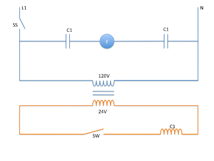
Going back to the first lesson in this manual you will remember there is line voltage and control voltage. The line voltage is the power supplied from the power company. This voltage can be at 120 Volts, 208/230 Volts, or 460 Volts. This voltage is great for running compressors and motors but it is not good for controls. The circuit in figure 23 shows a transformer in a circuit.
Control voltage is a lower voltage, in most cases this is 24-28 volts. Most controls can operate on the lower voltage more safely. It is much safer to put 24 volts into a thermostat in a house than using 120 Volts. The other benefit is the lower the voltage the smaller the wire can be.
By using a step down transformer it is possible to take this 120 or 230 Volts and reduce it to 24 Volt and power the control circuit. It is critical that the only place these circuits come together is in the transformer which isolates them by a magnetic field.
Your next shop project will use a 24 Volt control circuit to control two 120 Volt light bulbs with a relay.
Glossary of key terms
Primary: The load side of the transformer. This is the side that takes voltage from the circuit.
Secondary: The supply or source side of the transformer. This is the side of the transform that will provide voltage to a second circuit. The primary and the secondary side of the transformer are isolated from each other by a magnetic field.
Step Down Transformer: A transformer that reduces voltage from the primary to the secondary side.
Step Up Transformer: A transformer that increases the voltage from the primary to the secondary side.